Creating Profile
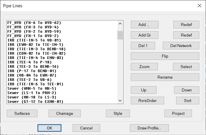
Drawing profiles can be done quickly by selecting the first, the last and the in-between nodes:
1- [Add] This button will prompt user to add profile line to the list, by picking the 1st, last and the in-between nodes.The default name will be the (
2- [Add Gr] This button to add a profile line for gravity networks by selecting the first and the last nodes only.
3- [Del1] This button to remove the highlighted profile from the list and delete it after pressing OK.
4- [Flip] This button is reverse the line; the line will start from the last node to the first node. The name of the line will be changed by reversing the arrow, but if the line was already renamed, no rename will occur.
5- [Zoom] This will zoom the screen view to the highlighted profile line in the layout.
6- [Select] This will zoom to and select the line pipes and
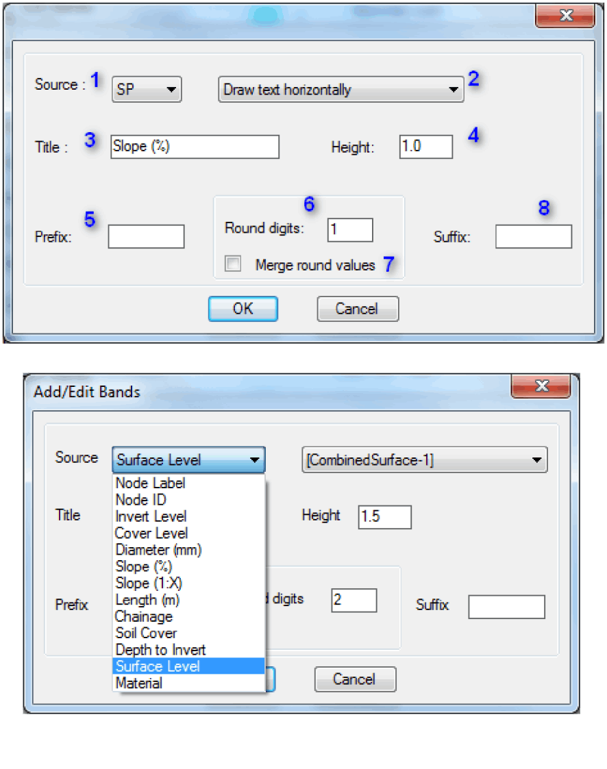
11- [Surfaces] This button will enable user to add/remove one or more surfaces to the highlighted line. The number next to the button indicates the number of surfaces to be shown on the highlighted profile. The top surface will be in one layer, the rest will be in another layer as specified in the profile settings dialogue.
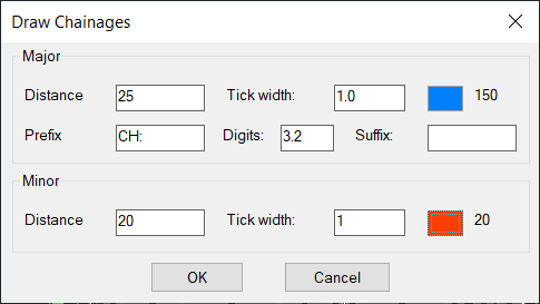
9- [Chainage] This button will create Chainages to the line
10- [ Style ] To select the Profile Style, for the highlighted prof
11- [Draw Profile] This will draw the highlighted profile line, user will be prompted to specify the insertion point.
12- [ Project ] This button will prompt user to select a 3d Poly to be projected on the profile, information of this object can be added to the profile bands.
The profile will be one block even if it is split into several lines based on the profile settings.
Profile Settings
Here user can customize the way the profiles drawn, the settings will be saved within the drawing and not to be lost when the drawing closed.
Below the is a typical profile example illustrated with numbers and text related to the setting entries in the Profile Settings dialogue box.
(1, 2) are used to set the Top/Bottom and Left/Right margins of the profile respectively.
( 3 ) This is to set the width of the left most column of the profile (the title of the bands) .
( 4 ) This is to set the drop under the lowest invert level of the pipes connected to this node.
( 5 ) Use this to change the shape of the node in profile, 0 to draw rectangular node, higher to draw top reduced cap shape.
( 6 ) profiles will be split into parts with length not to exceed the value specified.
( 7 ) Vertical to Horizontal Scale
( 8 ) Distance between points to be used to draw surfaces, the less number the higher accuracy and surface details
This will not affect the accuracy at the nodes as the will always be calculated not interpolated.
( 9 ) If levels are required but the surface was not covering this area, this value will be used by default
(10) To set the horizontal distance between profile views when split into more than one. Default is 5 x Title text height.
(11) if selected it will show crossing pipes of other networks if any.
(12) if selected it will show lateral pipes of the same network if they are connected to the nodes.
(13) if selected it will show the center line of the pipes between nodes
(14) if selected it will draw line connecting node cover levels, may not be required if a surface is used.
(15) if selected it will draw the Hydraulic Level if exists in the pipe properties.
(16) are used to set the text height of each text group as shown in the profile example:
(17) is used to set the text styles for all texts used except for the profile title text (18).
(19) is used to customize profile title using the variables in the drop down list.
(20) Shows the Layers Settings dialogue (see below).
(21) Shows the Bands Settings dialogue (see below).
(20) Layers…
( 1 through 12) are the layer names and colors of profile lines and texts, (6) is the layer to draw the first surface in the surfaces list assigned to this profile, all other surfaces will be drawn in the layer to be set in (7) entry.
21) Bands…
[Add] This button is to add Band data line to the profile, the band will be added above the highlighted band, the buttons [Up] and [Dn] can be used to move the band to the desired row.
[Edit] This button is to edit the band data parameters.
[Del] This button is to delete the band line, note that the profile cannot be deleted, it is the minimum requirement to draw a profile.
[Up] [Dn] To reorder the bands
Note: The details in each band row are indicative and may not contain all the settings of the band.
Add/Edit band lines
( 1 ) Select the band type from the pull down menu. A default values will be shown.
( 2 ) This menu may show an option to draw the data text horizontally, vertically or auto for some band types and may show a list of available Surfaces if the band type is (Surface Level ).
( 3 ) Here the band title can be changed
( 4 ) This filed is to set the band line height.
( 5 ) Prefix to precede the band value, if applicable.
( 6 ) This will set the band data precession by typing the number of digits, if applicable.
( 7 ) For some bands (e.g. Diameter, Slope) and for clarity purpose, values will be merged if they are similar and a dimension style will be used to show them. If this box was not selected, the actual values will be used and will not be merged if they are different even if they look similar when rounded. By checking this box the round values will be used and merged if they are equal although the real values are different.
( 8 ) Suffix to follow the band value, if applicable.
The Graphic part of the profile will show different dialogue box to modify some properties
The Band Title text and the Datum reference level, If Auto is checked the Datum will be calculated to be lower than the lowest point of the line by the value specified as ( 15 ) Profiles T/B Margins) in the first dialogue box.
If not checked the user must specify a valid Datum level, which must be lower than the one calculated in the Auto, otherwise it will be ignored.
Mobirise website builder - Find out