Edit Parts Common Commands

The commands ( EDL, EDP  and EDM) are common between Nodes and Pipes, the program change the context base on the fist picked element. In addition to these commands it is important to understand the selection set filters used by SmartUtils to make selection set more efficient.

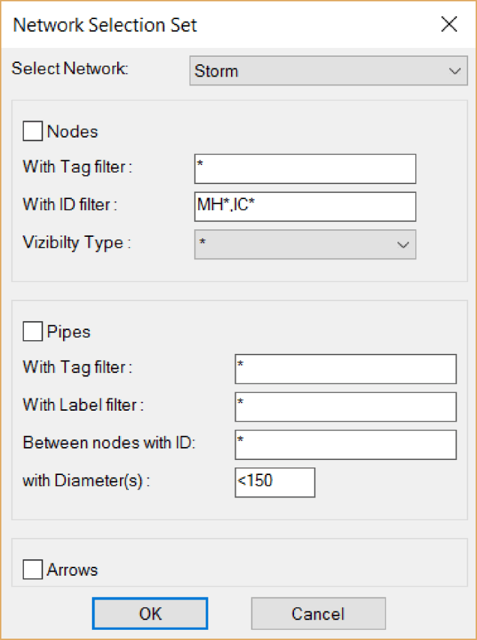
Filtered Selection Set

Prior to any selection users can type S to bring up the filtered selection set dialog where they can filter their selection using the following patterns similar to DOS wild cards:
Patterns Matches
* Any string
? Single character of string
# Single digit of string
@ Single alphabetic character
. Single non-alphabetic character
~ Anything except pattern
[ ] Any enclosed character
[~] Any character not enclosed
[-] A range of single characters
, Separates two patterns
\\ Single backslash
` Read next character literally by defining the node visibility type, a set of nodes


This filter is available as stand alone command ( NWSS ), the result of the command will be stored in the "Previous" selection set of AutoCAD.

su_nwss.png

Edit Properties ( EDP )

This command will edit properties of pipes or nodes. the command will respond to the first selected element to show the correct dialog. There is also an option to filter the selected network elements by typing S before selecting any element to show the filter dialog box. If the first selected is a node, the command will continue selecting nodes of the same network. Same is applied to pipes.

If the selection set was pipes:

In addition to layouts pipes can be picked from profiles, in this case the program will assume the user will select a segment (sequence of pipes) of the profile and will prompt for the last pipe in the segment, if only one pipe is required then the user must select it again.
The properties of pipes that can be edited with this command are:
Layout Color: by default the color is ByLayer, here it can be set to any value
Profile Color: Same as above, for the color of pipes in profiles.
Pipe Tag and Pipe Label: Pipe tags and label can have any text, by default they have no value. Changing Label or Tag will assign same value to all selected pipes. To assign sequenced Labels or Tags the commands QNUM and ANUM may be used.
Layout Style: Pipes can have their own layout style instead of the default style whic is set to "ByNetwork".
Line Type: The default is continuous and it can be changed to any available type, it can be set using AutoCAD standard command but this can be useful when combined with filtered selection set.

su_edp_pipe.png

If the selection set was nodes:
If one or more nodes are selected this dialog will popup. Users can change the following properties:
Text Scale: Annotation scale with reference to it's top left corner scaled here
Text Rotation: with reference to the block insertion point.
Structure Scale: with reference to the block insertion point
Structure Rotation: with reference to block insertion point. The Snap option set it parallel to the pipe direction.
Visibility: The node type (block visibility)
Node ID: This property to be changed with care since this is normally unique value and will affect any export/import operation. The button [?No] will help to detect the first available number based on the pattern in the Set to text field.
Node Label: This property can be set to any value.
Node Tag: This can also set to any value.
Layout Style: Here the style can be set to other than the default value.
Color in Profile: To change the color of the node in the profile.

Norte: It's important to use this command to change the block's dynamic properties mentioned above NOT the AutoCAD object properties box. Using AutoCAD's Properties box will cause AutoCAD to crash if many blocks are selected.

su_edp_node.png

Edit Materials ( EDM )

If the selection set was pipes:

The user have 3 section types: Circular, Rectangular and Channel Section.
Circular: Require diameter and thickness only.
Rectangular: Require height , width and thickness.
Channel: Require height, base width and side slopes in order to define the top width slope value, this value represent how many heights to be added to the side, 0 means vertical, 1 means same height value added to form 45 degrees.
if more than one pipe selected, use star symbol * to protect this field from being modified. 

su_edm_pipe.gif

If the selection set was nodes:

Circular, Rectangular and Null Structure are available. Null Structure has no dimensions or Materials to set.

If the selection set was nodes

Edit Levels (EDL)

If the selection set was one pipe:

Here user can change both levels or one of them then press ok, the Slope button is only for checking.
Pressing Calc button means other values are fixed:
- Pressing the right Calc button means the left value and the slope are fixed and the right value will be calculated.
- Pressing the middle (Slope) Clac button will calculate the slope by fixing the other fixed values.
- Pressing the left Calc button means the right value and the slope are fixed and the left value will be calculated.
Note: It is possible to use + or – to add or subtract values as highlighted in the picture. 
Apply changes to connected pipes at both ends is self explained.

su_edl_pipe.png

If the selection set was sequence of pipes in a profile:

Same dialogue box will appear but the nodes this time are the first node in the segment and the last one, pressing OK will apply the levels to all pipes resulting on straight line with the given slope. (here the network connection type will affect the way the pipes will be connected)

su_edl_seg.png

If the selection set was multiple pipes in the layout:

Then this new dialogue will appear:
1- If the levels are written in the Attribs of the node they can be copied before applying layout style as they will wipe out the attrib contents.
2- Fixed value for all pipes
3- Add to /Subtract value from all levels of the pipes selected.
4- Get the levels form a surface by specifying the surface and the depth to the (invert/crown/center)
Note: levels to be set are based on the connection type of the network, the dialogue will show the correct point to be set whether it was on invert, center, or crown of the pipe. 

su_edl_pplay.png

If the selection set was nodes:

Cover Level
- Set all Cover Levels to this fixed value.
- Copy the value for attrib of each node,
Note: Attrib values must not be set manually to the nodes as they will be lost when applying layout styles.
- From Surface if any.

Connected Pipe Levels
- Select an type the value to rise (+ve) or lower (-ve) the levels of the connected pipes.

Sump Drop
Sump is the distance between the lowest level of the connected pipes to node and the bottom of the node.

su_edlnn.png

© Copyright 2021 Ai Productions - All Rights Reserved

How to set up your own website - Click now